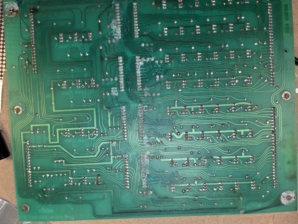
I’m working on a Stern Hot Hand. I was not sure if I was going to replace my lamp board so I could use LEDs, or keep my original lamp board and keep the game original. Then I saw the backside of my lamp driver for the first time.
I’m working on a Stern Hot Hand. I was not sure if I was going to replace my lamp board so I could use LEDs, or keep my original lamp board and keep the game original. Then I saw the backside of my lamp driver for the first time.
My new-to-me Counterforce had most of the lamps in the insert panel (behind the backglass) missing. I grabbed my supply of LEDs and populated the lot. The glare was so bad it made the game hard to play.
I replaced a bunch of the LEDs with #47 incandescents, except where I liberally used #455s, the blinky bulbs. I love these — although I see they seem to be out of stock at several suppliers. I suppose they will go NLA soon. But I have them for now, and I love their randomness and the noise that they make. Plus, since they’re usually off, the glare is greatly reduced.
When I cleaned the playfield, I upgraded several lamps to LEDs–Nifty frosted warm white, generally, since I still have a stock of those. But a lot of the playfield holes won’t accommodate the larger plastic ring on the LEDs, so I used #47s.
Initially, I didn’t know if I would LED the controlled lamps or not. But I had a couple I wanted to brighten up, and they looked so good, I started installing LEDs in all the inserts. Counterforce has quite a few non-controlled inserts — around 12 that are on when a corresponding drop target is on. All of these are yellow inserts, so I used TJ’s trick of lighting them with a pink bulb. A yellow LED bulb tends to look washed out. The pink ones look great. They look really hot in the purple inserts that Gottlieb used for extra ball.
Another 28 lamps are stepped up with an under-playfield transistor. These provide the incoming bomb lights. I haven’t done these yet, but I think they’ll look great when done.
But on my way there, I’m soldering shut a bunch of lamp sockets, or maybe replacing sockets. This is a trick I learned from Tim Arnold’s handouts a long time ago. Here’s a PDF. On old sockets, the press-fit loses its will to press-fit. But a drop of solder on the joint provides connectivity and can revive a dying lamp socket.
So far I’ve had a couple that look great with the upgrade.
I plan to do this on the bus sockets used for the bomb lamps and the bonus ladder, both of which are irreplaceable, have lots of individual wire connections, and quite a few loose sockets.
[Originally written in early 2021, minor updates in early 2024.]
Chris refers to the Gottlieb drops as the Cadillac of drop targets. I’m not so sure, but they do play well. Drop targets are an annoying mechanism to work on, especially those with added features like trip coils.
Williams drop targets have a failure mode I call slo-mo drop targets. You smack one with the ball, and instead of clicking down, it sinks slowly into the playfield. This comes from dirt. If they’re really dirty, you can hit one, the ball can move far away, and then it sinks. It’d be cool if it happened on purpose.
I got this Gottlieb Counterforce. And it had slo-mo drops. I’ve never seen this in a Gottlieb game. There’s nowhere for the dirt to hide. So, while shopping out a bunch of stuff wrong with this game, I did the drops.
I replaced all the targets (which didn’t match). I followed PAPinball’s guide, which is very good. I didn’t expect this to fix anything, but I hoped it would. It didn’t.
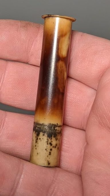
I cleaned the coil sleeves for the two reset coils, which didn’t really help. So I removed the bank and did a deeper (but still half-assed) cleaning. When I was done, I still had slo-mo targets. (This sleeve is cooked, but it still works OK. Perhaps I’ll replace the coil, but for now, it’s working fine.)
It became pretty clear the problem was with the reset bar not sinking. If one target was already fully down, any other target would drop quickly. But if no targets were all the way down, you’d get slow action because the drop target had to push the reset bar down. So once the reset bar was down, targets would drop quickly.
On this mechanism, there is some freedom to adjust the coil in the bracket. Coils can be twisted slightly relative to their plunger and the reset arm. The coil needs to be square to the bracket, and both coils need to be at about the same depth. The coils can be adjusted slightly so the reset bar doesn’t over-extend the targets out of the top of the playfield, but they need to be square to the mechanism to work correctly.
Now, as drop target banks go, this one has all the bells and whistles. There are seven drops, but there are seven trip coils on the top, too. These are triggered by the computer when it wants to drop a target. In Counterforce, these are triggered by rollover switches and standup targets scattered all over the playfield. Each drop target has a sense switch, but it also has a lamp voltage switch used for “when lit” indicators for the trip switches, and also for the big falling-bomb gimmick.
On my game, one of the trip switches didn’t trip. This appears to have been a coil that was open. The coil was A-18642, but research indicates there are a couple other usable substitutes, one of which was in Chris’ parts bin. So that’s what got used. (Pinball Resource can identify the substitutes, if necessary, but they also have the correct part number.)
I was able to identify that this coil was open by using a multimeter. In the diode setting, I was able to measure the diode of the bad coil — but not of the good coils. For the good coils, when I try to measure the diode, I measure the coil instead. So that was my indication that the coil was at fault.
So far, so good. Resoldering these coils is kind of a pain because there’s so little clearance in this mechanism.
My Counterforce is still torn apart waiting for other parts, but the drops all now work correctly.
So:
This all applies mostly for Gottlieb drop targets. In any case, I haven’t generally had problems with them once they were rebuilt in home use.
On Williams games with the horseshoe mechanisms, the problem is the horseshoe mechanism. Those things are terrible.
On Williams games with optos, and I suspect those with leaf switches at the bottom of the column, they get dirty and sluggish. I cleaned my BK2K’s targets once and they’ve been great, even after the game was operated for six months at the PPM.
On old Stern games, there’s only one spring that drops the target, so it can be twisted by the spring. If you can get that adjusted correctly, they work great, and can be swept by a good shot. I love these.
Old Bally games are similar, but I don’t have as much experience with them.
I have seen two different drop mechanisms on new Stern games. On my WPT, there’s a service bulletin to enlarge the catch shelf for targets that has cured most of my woes. On my Simpsons Pinball Party, I had a loose connection — otherwise it’s been quite reliable.
I got a Bally Star Trek back in November 2014. I knew the computer would be corroded, so I pulled it and removed the battery. I didn’t leave myself enough lead and I don’t think I’ll ever get both terminals out. There are quite a few missing traces and damage. I hurt my hands trying to get the damage out.
I picked up another board from a sale on RGP, also from a Star Trek, that is a better candidate. It only had a little corrosion, but it doesn’t boot.
As a stopgap I picked up an Alltek CPU. I want a -35 CPU for some reason, so I’ll probably still fix the clean one when I have a chance to get some help.
When checking out the head, I found my driver board (one of the nice Stern ones with really elaborate silkscreening) was missing two transistors. I replaced them. While I had the board out, I removed the filter caps for the high voltage and the +5V. The +5V cap was bulging—so its days were numbered anyway, as if being 34 years old wasn’t enough reason to replace it.
Power cord was missing ground prong and was a little damaged, so I replaced it.
My lack of skill at drilling out the lock left lots of metal shavings in the game, and since the lock is over the rectifier/transformer assembly, I pulled it and vacuumed out the head.
The sound board was removed to make it easier to get the transformer out, so I re-capped it. I re-installed it and the game had a loud hum tied to the number of lights on. I removed the sound board a second time, and discovered about a third of the header pins had obvious cracked solder joints. I resoldered them and plugged the board in and it worked great. Then I screwed it down and the hum was back. I’m guessing I have a floating ground somewhere. Given the obvious age of the header pins, that is not surprising.
I was missing a full row and a full column of switches, including the outhole and the saucer. (When I bought the game, the seller told me that it didn’t work. He didn’t know about any of the other problems.) I re-pinned the connector to the MPU and I have most of the switches. I suspect cleaning will make the rest work.
So, it plays. Just not well.
After I wrote this, the draft sat around for years. So did the game. That’s the problem with old games: they are great for storage. Around 2017 I borrowed the SDU board. It sat outside the cabinet for three years until I got around to re-installing it.
In 2020 at the beginning of the pandemic, I got an offer for the game as-is. Since I had too many projects, I sold it, and a CPR playfield. And I finally have some space for the Eight Ball Deluxe project.
A few years (!) ago I bought a Spy Hunter. It played blind.
I got this game as a sweetheart deal, and I got a great price because it wasn’t working. It belonged to a friend who used it for party rentals. I knew it had been well maintained. Must be a loose wire or a fuse or something.
I talked to Chris, who said that if I pulled the boards apart, everything would work until the game got moved. Well that sounded pretty annoying. So, as I am wont to do, I bought some parts—in this case, a set of new interconnect cables—and put them in the cash box for some other day.
Well, that day was in late 2019, when I conned GMike and I into taking a look at it. Still no video, and no obvious reason for no video. So we replaced the interconnect cables. This is a pretty large pain in the ass, because the MCR III system is such a convolution. Power comes in one end of the board stack, I/O comes in the other end, and all the spring tension on the connectors is so tight, they’re nearly impossible to take apart.
GMike and I got the boards apart on the dining room table, cables replaced, back together—same thing. I texted the previous owner and got the scope out and handed it to Mike, who confirmed the video pins weren’t videoing. I have a pattern generator for the monitor, which proved it was OK. The text conversation went back and forth a few times until I realized the video signals weren’t connected to the CPU, but to the Super Sound I/O board which, for some reason, has a connector with exactly the same connector as the CPU.
So we moved the connector over and played some Spy Hunter.
Next problem: bad power switch. I think it had just mechanically failed and wouldn’t stay off. Unfortunately we had to change the QD connectors from .25 to .187, but they work just as well.
Last problem: no saved settings. There are two types of difficulty setting in Spy Hunter. One is DIP switches and controls how long the “unlimited cars” time is. The other is in software, and coincidentally, also saves high scores and bookkeeping.
The battery had long since been replaced with a supercapacitor. But when the power was shut off, whether or not the card rack was connected to the power supply, the available voltage dropped to nothing quickly. So, GMike put a new cap in it. That would at least hold voltage with the power off. But with the boards connected, voltage would drop.
Chris suggested replacing the 6116 on the CPU, or the capacitor and diode on the power supply related to the battery. I had the cap and diode, so I replaced them. I would have done the 6116, but it’s so difficult to get the card rack out, I put it off. I got some 6116s from Chris on a visit to his shop, and actually ordered an NVRAM so that I’d only have to go at this once.
Tonight, though, rather than put the NVRAM in, I wanted to get the 6116 to work. It’s so difficult to get the ribbon cables off, I stopped trying, and learned to work with the boards connected (very carefully). Actually, the Spy Hunter is in the garage, and the available low-static workspace I had was a pinball machine in the house, so I just took it inside. Where it’s warm.
I got the stack apart and couldn’t find the 6116 on the CPU board. So I looked around and saw that it’s actually on the video board. I put in a new chip, and no change. (OK, one change: the video connector is so hard to get on, I missed pins and corrupted the video. Other than my heart breaking that I just broke the game, no problem.)
So I put the NVRAM in. It barely fit in the stack. Plugged it back in, and the sprites were either missing entirely or corrupt. Uhoh. Had I changed the wrong 6116? Yep. The correct 6116 to change is on the CPU board, at 5G, and this was documented by the vendor. I had missed it because the original chip had a weird part number. So, on my third reassembly of the day, I put the right chip in and reinstalled, and things appear to be working!
(So I can’t really say that the NVRAM didn’t fit. I mean, if you put it in the wrong place, it doesn’t fit. That isn’t helpful. However, the NVRAM will not work as video RAM. That’s also not helpful but is something of a fun fact. I guess.)
I finally increased the difficulty from default 3 up to maximum 9. It’s a more interesting game. At 3, there are a lot of times where there are no spy cars to attack. At 9, there are spies almost all the time. It’s great.
I re-checked the voltage, and with the power off, it stayed around 4.80, a big change from the various broken parts. So far, the cap appears to be working.
I have more or less finished a shop job on my Simpsons Pinball Party over six years in the waiting. One problem that I have been frustrated with was the drop target bank got confused sometimes and would award “drops completed” several times. Careful observation over an extended period of procrastination and play revealed that the middle target seemed to be at fault.
I actually went as far as buying some new microswitches, just in case one was flaky. Then I remembered to always look for a bad connection first.
The diodes on these switches are mounted on a terminal strip a few inches from the drops. I thought for sure one would be cracked, but they looked fine.
So I pulled the drop target bank out of the game, and one of the QD connectors fell off of its switch lug. I used pliers to squish the switch a little bit together and slid it back on. So far so good!
I read on the Intarwebs that when a Tommy can’t kick the balls with the auto fire kicker, it means the mechanism is worn out. DE had a couple different mechanisms and Tommy. The original parts are NLA but you can retrofit the newfangled mech from modern Stern (or Sega) games. Pinball Life had them cheap so I bought one months ago and procrastinated installing it. Even though the 1994 mechanism is pretty bad, I didn’t relish adding a bunch of new holes to the playfield, and I had been putting it off.
But I looked carefully at my original mech today and it had only a little wear, but lots of dirt, so I just cleaned it instead. Now it kicks quite well!
This mechanism on my game has two different pivot points with a lot of metal-on-metal contact, so naturally it got some much needed oil as well.
Your mileage may vary, but it’s worth checking. The link above mentions the design is bad, and it isL DE went though a bunch of different autofire kickers before finding one where the shooter rod doesn’t plunge into the mechanism. So the swap will be necessary––eventually.
Now to figure out why I’m bad at the game.
Tonight’s lesson for me in vintage arcade collecting: Just because I’ve owned a game for 16 years doesn’t mean I’ve ever really gone through it.
My Robotron had developed intermittent RAM errors after many reliable years. Sure, one of the 24 (!) RAMs might have gone bad, but it seemed equally likely to me that the power supply was probably getting flaky. I got about 4.7V across a cap on the computer board, and after reseating a couple connectors (not a proper fix, I know) I got 4.9. Good enough, and the RAM error is gone.
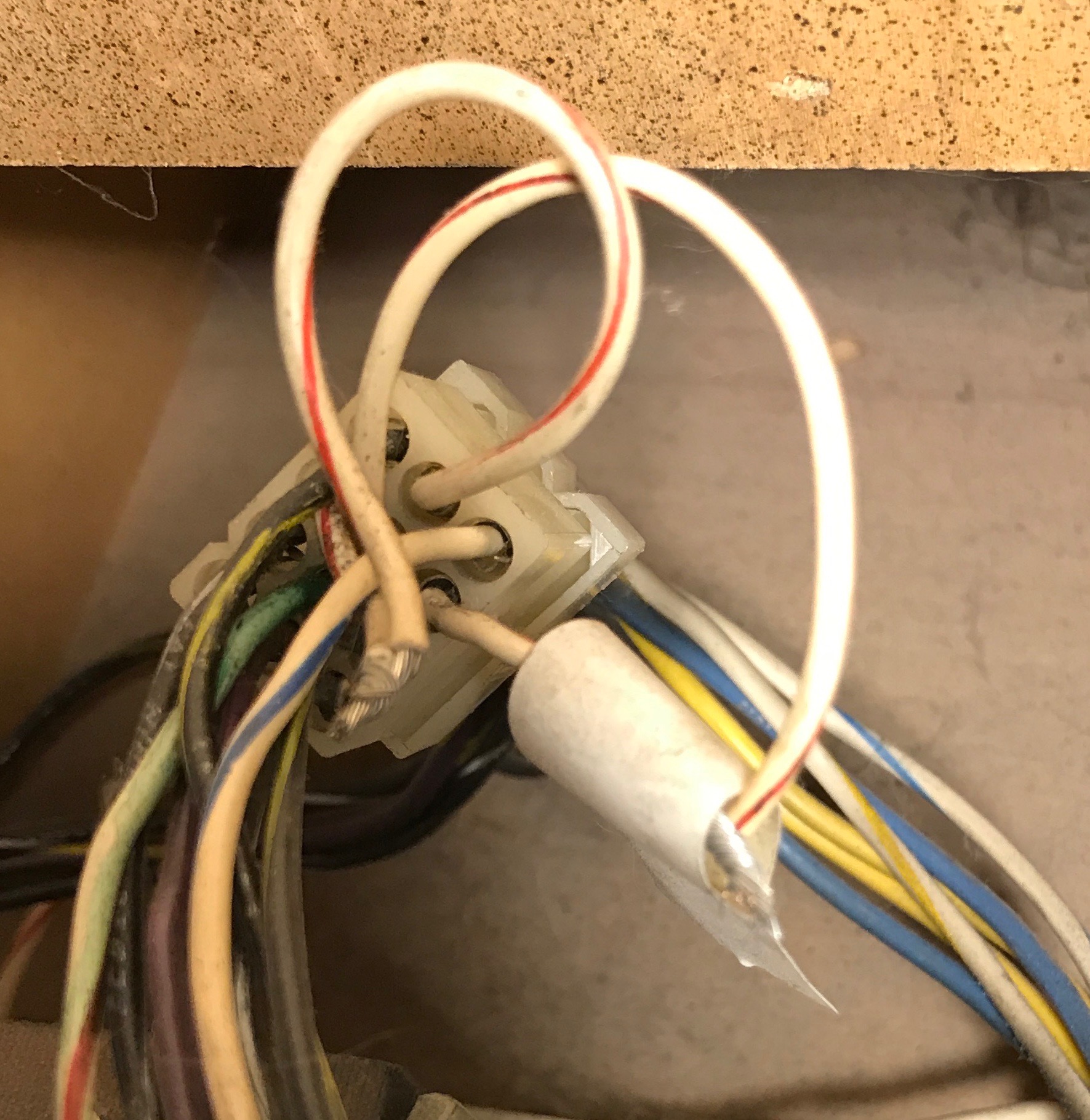
Looking around, though, I saw this. This is part of the transformer strapping in the main power connector. Why were the wires cut? Why are the wires just twisted together? Why does only one wire have electrical tape? Why is the electrical tape applied wrong? The only answer I am sure of is why the electrical tape is falling off: because electrical tape is terrible. Maybe there were wire nuts on here at some point, but I doubt it. Some of the crimps were not great, either.
The power supply still needs some attention, though. There are some other suspicious splices and a bypassed connector. Oh, well; for now, it’s playing fine.
A decade ago, I tried to put one of Clay Cowgill’s multigame kits in this cabinet. It never worked correctly and I took it out. I wonder if the +5V was a little low even then. Perhaps I should give it another shot.
Edit: A year later, it turns out this wasn’t what was dragging the +5V low. I suspect the bridge rectifier was out. But this was still bad 🙂
My Tommy was really clean, and played fairly well, but I have noticed a few things.
The first and most glaring is the damn autoplunger. I hadn’t remembered that this one is different from the ones on my Simpsons Pinball Party, Star Trek, and WPT. (The Star Trek one is different from the other two.) I have the later model, according to the manual.
The problem with this is that the shooter rod goes right through the kicker. Since my mechanism is a little worn, it’s not consistent. I have made some adjustments, but I’m not satisfied with it. I have read that the new mechanism can be installed, and I’m going to do that at some point.
I put in a weaker spring (but one grade stronger than what the manual says) to make the skill shot easier.
I put in a long barrel spring to keep the plunger out of the kicker’s way, but this doesn’t work that well.
I put a little rubber bumpon as an extra stop in the mechanism so that the kicker would remain vertical, and the shooter rod would more easily clear it.
On my autoplunger, one of the tabs is broken off the coil. This is probably because the coil was installed with the lugs to the right, and it got scraped several times by raising and lowering the playfield. The cabinet is damaged. I changed the lugs to point downwards, and move them away from the coil stop, but ultimately I’ll replace the coil when I replace the mechanism.
I had some random multiball problems. Specifically, in situations where the game should have kicked a ball into play (in particular the Encore ball saver) it would release a ball to the trough upkicker, but not fire. No big deal, the actuator on the switch next to the trough ball release (upkicker) needed some adjustment.
Pop bumpers needed their switches cleaned. I also re-gapped them and put in new spoons. The DE brackets are easy to work with, but they just don’t kick as well as a Williams mechanism.
Lubricated the spinners. Much better.
Software upgraded to 4.0. I will try the unofficial 5.0 ROMs soon. I got these from Matt’s Basement Arcade because I don’t have my own burner here.
NVRAM installed. I used an anyPin RAM, but I didn’t put in a new socket. Seems OK so far.
Skill shot didn’t work right. Sometimes it worked, usually it didn’t. A broken diode on the rollover switch in the subway meant that sometimes it saw a skill shot, and sometimes it saw a Tommy hole shot. Solder fixes this nicely.
Prop rod had been removed and left in the bottom of the cabinet. I took a guess as to how to mount this and mounted it.
One of the playfield stands was missing, and the hole was damaged. I never thought I’d wish for the newfangled rods on a Stern game, but here we are. I got some of the ones from Mantis Amusement that have more attachment points. I promptly bent one, but they’re still better than the factory.
I have been playing this a fair amount and it’s kicking my ass. The slingshots, in particular, are especially cruel. They fire the bar into the 3-banks, and the 3-banks fire the ball into the outlanes. I guess I need more practice.
Exactly what is the title of this game, anyhow?
I have one that I picked up that’s really clean. It’s not perfect, but it seems to have been well cared for.
This really means is that I now own a game with a TY-FFASI board in it again. I had a Back to the Future when I bought this domain, but I sold it a long time ago.
[Edit: Then I sold it. In late 2021, I bought a Rocky & Bullwinkle.]