To my surprise, most of my current collection is Stern games, and I think they can all be improved a little with a few mods.
I’m not a big fan of playfield mods in general, although I have done a few here and there. I find that they make the game harder to work on, they don’t affect play, and a lot of times they’re distracting. But I do have a few generic things I like.
Headphone Jack
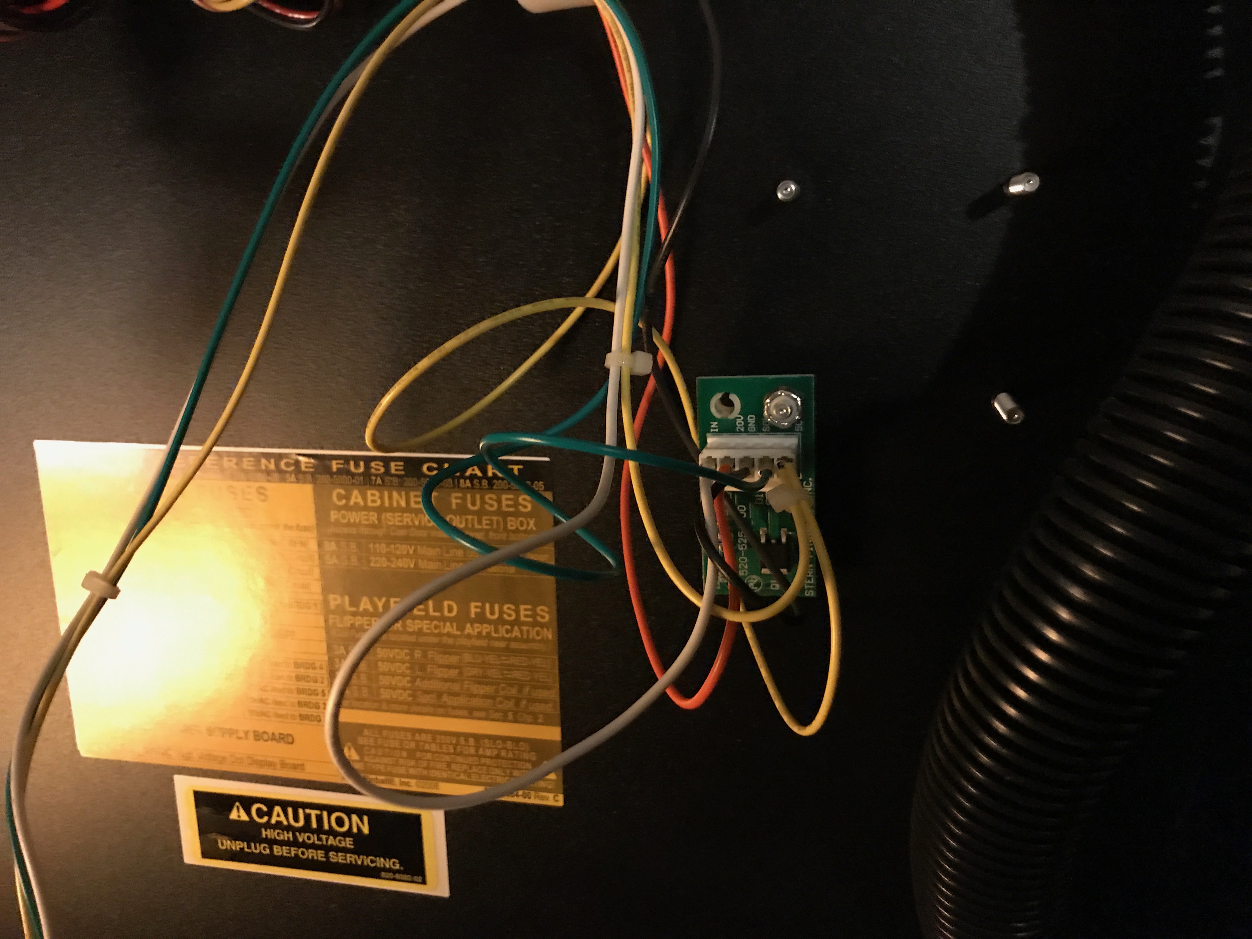
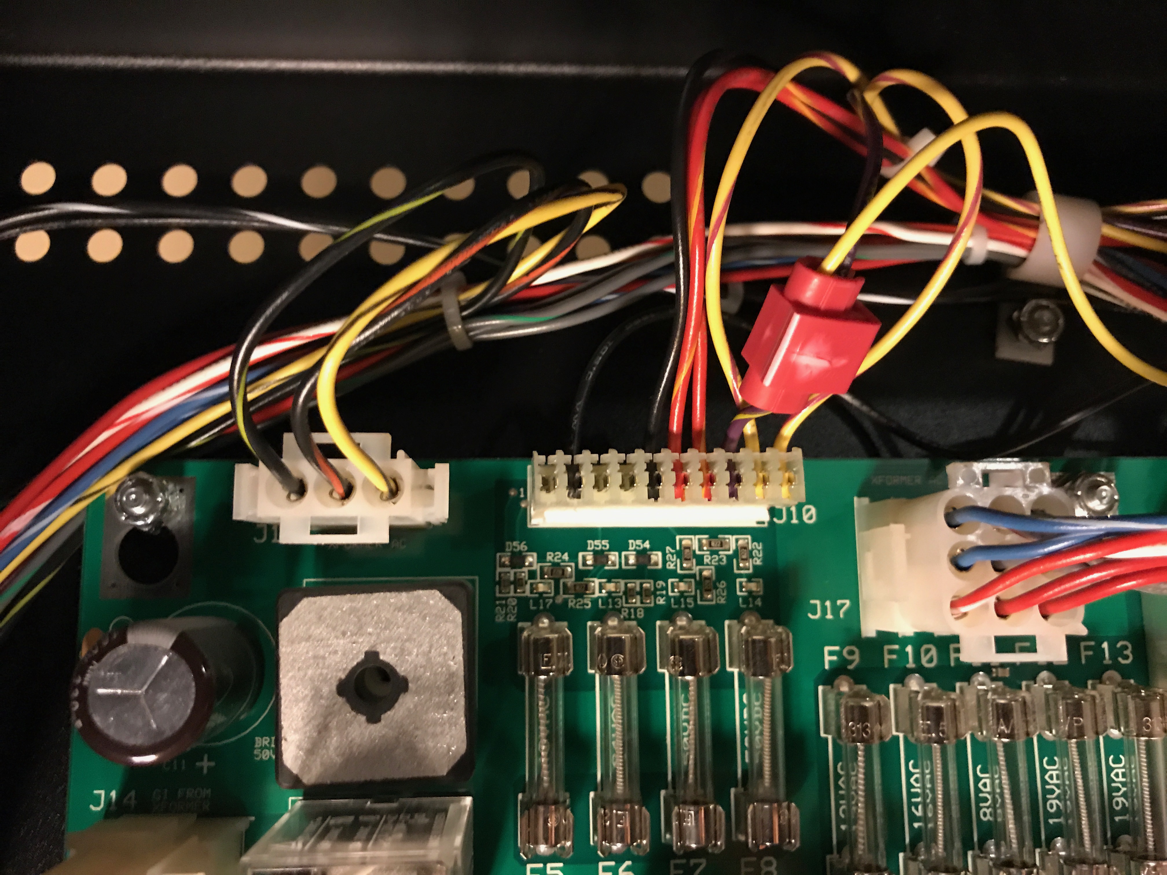
On all SPIKE games, Stern has a good kit for headphone jacks. I like these for two reasons. First, headphones work and annoy my family a little less. Secondly, and perhaps more importantly, headphone jacks mean the volume control is on the outside of the game, and obvious. SPIKE games differentiate between headphone volume and game volume. The kit is not difficult to install, and is reversible, should you resell the game to an operator (just save the blanking plate in the cash box).
I’ve used some of the aftermarket headphone kits on Whitestar and SAM games. These are good, albeit not as good. In particular, they do not auto-mute when headphones are present, nor do they adjust the volume differently for speakers versus headphones. But they’re still good kits. My kits came from Pinnovators. (Note that these depend on both the board system as well as the coin door. Early games have a different blanking plate.)
(Unfortunately I also bought a volume control gizmo that fits into the tournament button hole. I can’t speak for it, as the headphone kit was better for me.)
Knocker
I’ve written about this elsewhere on previous occasions. I miss real knockers, but since Simpsons Pinball Party, Stern has provided a path for installing a real one. Pinball Life has a knocker kit that I recently installed on my Foo Fighters. (Amusingly, they still refer to this as the “Q24” option, despite the fact that Q24 is a Whitestar relic.)
Tournament Button
Starting from SAM games1 (WPT), Stern added a Tournament Button. On the first few games, like WPT, this was wired into the lockdown bar. Unlike current games, the lockdown bar has to be unplugged before it is removed, which is a real pain when working on a game frequently or even clearing stuck balls.
Cliffy makes a relocation kit that I installed on my WPT that I absolutely loved. (Without this kit, my tournament button spent most of its time simply unplugged.) This also meant putting a blanking plate into the lockdown bar to plug the hole. (At the time, Stern said they would sell a lockdown bar sans hole, but I never found that part before I sold my WPT.)
On later games, including my Star Trek and my Foo Fighters, there is no included button, but the wiring harness has connectors for the button, and a blanking plug is in the cabinet just below the start button. This is a little harder to install since the connectors are pretty well buried in the wiring harness, but I mean it’s a 20 minute job instead of a 5 minute job. The button is somewhat more interesting than the blanking plate.
The buttons are available from the usual suspects. (Note that I have not verified this part is the only part needed, and that the PBL price is currently less than half of the Marco price.)
Note that the tournament buttons don’t do much in home use. I just hate blanking plates for some reason.
I Avoid Shaker Motors
On my Star Trek, I installed a shaker motor. My kids were pretty young when we got the game and the noise bothered them. I didn’t feel that it helped the game experience, so I haven’t bothered with another one.
The kit is easy to install and not expensive, but mine sits in my Star Trek, disabled in software. Neither my Batman 66 (since sold) nor my Foo Fighters have shaker motors, and I don’t expect to install them.
Bonus Other Stuff
I changed the shooter spring in my WPT to the wimpiest one I could find. I sold my WPT to a friend who changed it to an even wimpier spring. But on my Simpsons, I think that it plays better with a stronger spring.
I have yet to replace my fluorescent tubes with LED tubes in my pinballs, but I keep meaning to. I did do this in some video games and I’m very happy with it.
I also generally like LEDs in GI for older games, which tend to be a little dark. Sometimes I stick with incandescent lamps in the switch matrix, and sometimes I change them to LEDs. (I use pink bulbs behind yellow inserts, which look great; otherwise, yellow bulbs behind yellow inserts tend to look washed out. Thanks, TJ!)
- The TOPS kit predates even SAM games, so some Whitestar games can maybe also take the button. But the TOPS kits aren’t that common, and I haven’t tried it. ↩︎