Installing a knocker in Stern’s Star Trek

I have had a Star Trek (Pro) and the parts for a knocker install, for well over two years. I decided it was time. I think this general plan would go for any metal-head game.

Get a real manual from an old SAM game. This is helpful in finding places to pick up the needed voltages. I used WPT, because I have one. Stern manuals are terrible after about 2008, but they were superb before that.

To tap voltages off existing connectors, get an IDC punch-down tool for .156″ pins. The trick to these is to run the wire into the connector just far enough. If it’s too far, it won’t punch down on the far side, no matter how hard you push.

Star Trek never had a high voltage board for its DMD, so there are some mounting posts in the head not being used. Maybe it’s different in the LE. I installed the same step-up board that I used in WPT and Simpsons, except it now requires +20V. I just put it on one post and held it down with a #8 nut.

The real pain point in installing the knocker is figuring out where to pick up the needed voltages. The 520-5254-00 step up board requires +50V, +20V, solenoid ground, solenoid input (from Q24) and solenoid output. (Older versions of this board omit the +20V but sometimes pull in at power on. Like a System 80 game!)

The cable dressing here is pretty terrible. I may have to re-do this due to poor crimping anyway, and if I do, I will trim all of the wires to the same length and dress the harness neatly.


+20V is available on J7-1, right next to another source that the game actually uses. In my Star Trek, it’s a fat orange wire. I suspect most SAM games have available +20V pins.


Solenoid ground is available from J10-2,4,5. On Star Trek, pins 2 and 4 are not populated, so I stuffed a wire into pin 2. It appears the game generally uses black for this. I suspect most SAM games have available grounds.

+50V is not as easy to get on Star Trek, as there are no spare supplies. On WPT, the dedicated magnet supply wasn’t used, so there was an unused pin in the J10 connector. Star Trek, however, has a magnet. I tapped the magnet with a suitcase connector (Scotchlok). I had some trouble getting this to make contact. I either didn’t squeeze hard enough, or the second wire slipped out of position before I clamped down. In either case, next time, I’ll check continuity immediately before moving onto the next step.

I also crimped two wires into the +50V pin for the step-up board so that I’d have a +50V wire to feed the coil with. I probably won’t do that again. Another suitcase connector would have worked just as well. (In my WPT, I fed +50V to the coil, then daisy chained it to the step-up board, which is a better idea when putting the knocker in the head.)

I ran a long cable with three wires out of the head and into the cabinet. One wire picks up the Q24 output and gives it to the step-up board. One is +50V and one is the output from the step-up board to fire the solenoid.

Knocker mounting in cabinet

Knocker mounting in cabinet

I screwed the knocker in the bottom and firing at the cross member near the coin box. I used screws that are a little too long and pierced the bottom of the cabinet. The cabinet bottom is not great plywood. I may change this over to T-nuts in the future. I believe I based this particular mounting on APB Enterprises’ directions on how to mount a knocker for their kits. For my WPT mount, I eyeballed it and it’s relatively close to the coil–and wonderfully loud.

If I make any further changes, or I do this again, I want more connectors to make the harness a little easier to work with and debug. Having the connector near the solenoid makes cable management easier. Having connectors for the patches into the existing connectors would make removal easier.

Another possible improvement: Does the shaker motor offer a place to hook in for +50V?

Tagged ,

WPT shop job initial notes

(Looks like this got written years before it got posted, somewhere around 2015.)

Got a WPT back in late October [2014]. I’ve been playing it, but it’s obviously in need of some love. Decided it was time to start major shop job instead of whatever I should have been doing.

In this case, it starts with the statement: “I’ll just take the upper playfield out in preparation for re-rubbering.” When I get the flippers out, I discover they need a rebuild. All of the rubber is old and hard, and a few lamps are out.

Right ramp has busted welds. Very dirty around pop bumpers. A massive amount of dirt near the upper left flipper, like some rubber has been getting ground up.

Start disassembling and found a couple wire ties in places that were not supposed to have wire ties.

All four flippers are egged out.  You wouldn’t know it on these Stern games, since both of the ramps were still make-able shots, but there must be some flipper power missing.

Two welds are broken on the right ramp.  But I have a friend who can weld enough to fix it.

Upper playfield is very dirty. I could polish it. Or I could install a new part.

I’m switching to the overly bright LED bumper caps on this game. I usually avoid this kind of mod, but in this case, the under upper-playfield area is so very dark, I think it’s called for.

So far I’ve got one ramp out and two wireforms out.

[I got it back together. I installed a new upper playfield. Probably worth it. If these aren’t clean, the “jail” lock doesn’t work right.]

Tagged

Installing a knocker in Stern’s World Poker Tour pinball

I just installed a knocker in my World Poker Tour. I used Stern’s step-up board, the one that is used for the kickout from the bumpers, available from the usual suspects. I got most of my information from this page.

A few random notes:

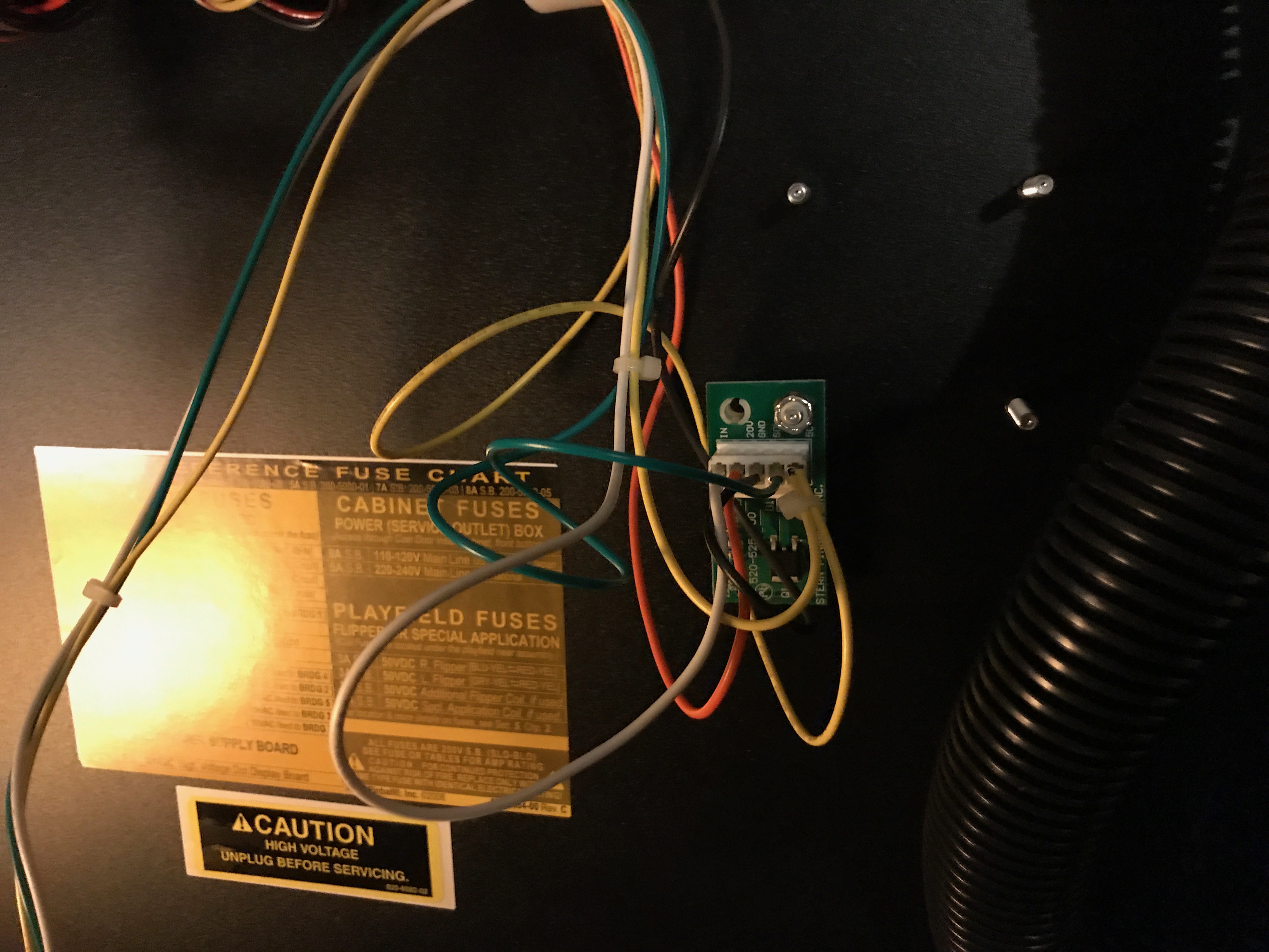
I used a 520-5254-00, available from Pinball Life, and documented in the WPT manual.  Because the knocker drive transistor can only sink 20V, a step-up board is required.

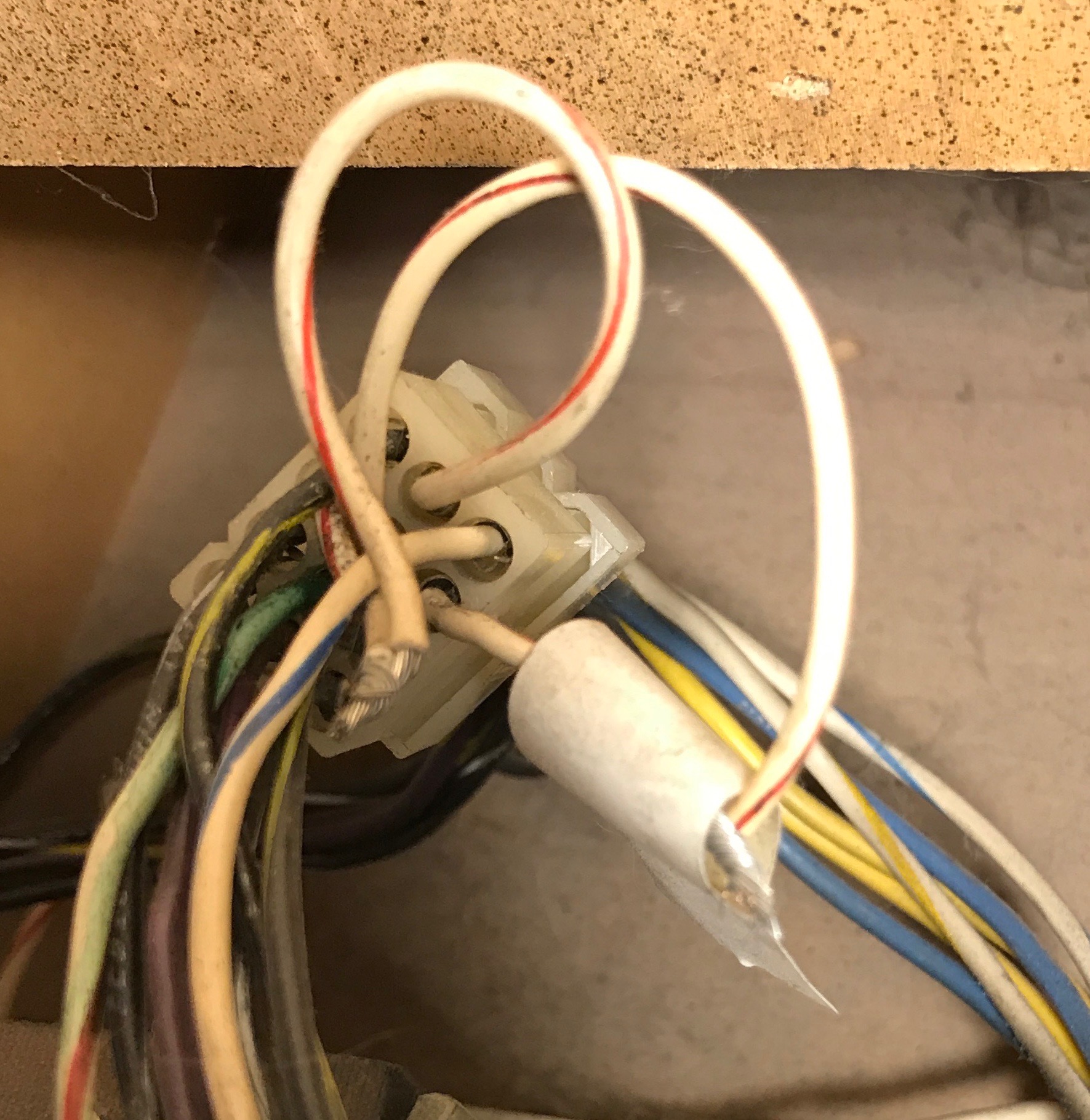
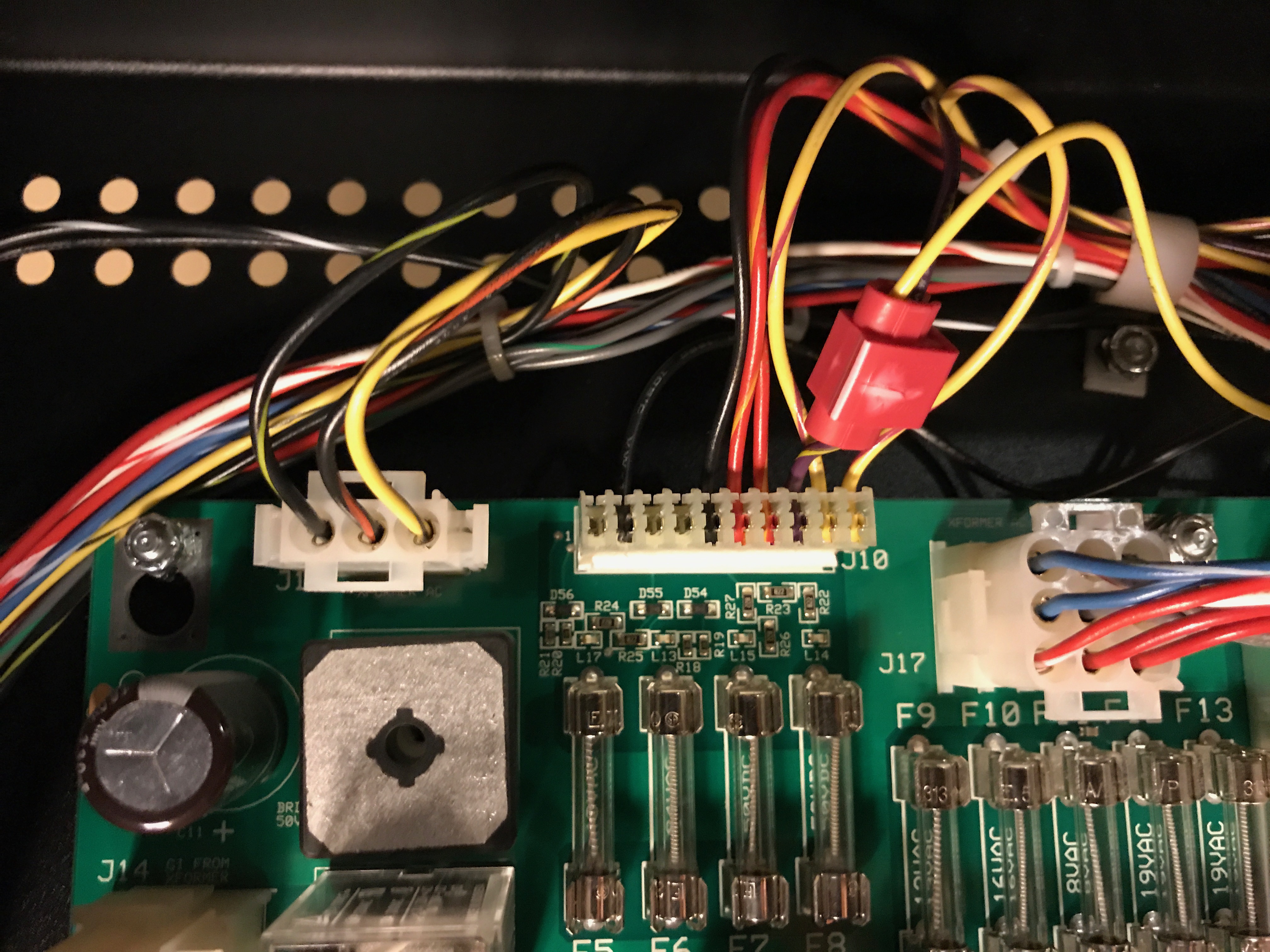
Three connections to the game are required: +50V, solenoid ground, and signal. Okay, you could probably use +20V if you wanted a wimpy knock from a wimpy coil. You can source the signal from the connector under the playfield that is used to drive the coin counter that nobody installs. +50V and solenoid ground can be found on J10. On WPT, it appears that pin 8 is not used, but it is fused by F7. Great deal! Three pins on J10 offer solenoid ground.  I used pin 2, but 4 and 5 would have worked. (You can pick up ground anywhere, but it is probably better to pick up the officially blessed solenoid ground.)  I happen to have an IDC punch-down tool.  I’ve had it for fourteen years, and now I’ve used it.  I didn’t have to solder anything (other than the coil) because I picked up all of the connections from connectors that already existed, which makes for a nice clean install.

I installed a Williams knocker, in the head. Mine was apparently from a High Speed, but it’s the same mechanism Williams used until they gave up on knockers.  The geometry of the Stern head leaves a lot to be desired from a knocker perspective. I will probably install the next knocker in the cabinet, and even that can be trying as I have discovered previously.

I put the head in the upper-right mounted to the side of the cabinet.  This was a tight squeeze for the assembly, and it was hard to install and it will be hard to remove for service.  I mounted the knocker on a block of scrap wood, then screwed that to the cabinet.  I don’t like the adapter block, but because of the diagonal brace in the corners of the head, a the knocker wouldn’t have clearance if it screwed to the head directly, and there’s no room for it on the back of the head.

I set the Q24 option to “knocker” and the “knocker volume” to off.  I discovered the “knocker” test drives both the real knocker and the fake knocker and it’s loud as hell. There is no other test for Q24.

Next time I install one of these, should I ever get another Stern game, I’ll probably try the Gottlieb knocker.  It doesn’t require a separate strike plate.  Running on +50V, it’s probably not as anemic as in a Gottlieb game. Or, perhaps I’ll mount a Data East-style unit in the head, down below the computers, where there’s space.

A modern Williams knocker fires up and has no spring.  Bally, Data East/Sega, and old Stern Electronics knockers fire at the side of the cabinet.  The bracket used for Data East is the same as Williams, but the plunger is different.  Old Williams knockers, like on Firepower, and Gottlieb knockers fire at their own bracket, and are mounted in the cabinet. Stern Pinball has never used a knocker.

The sound of a Stern knocker is different than a Williams knocker.  It’s more of a thud than a crack.  I suspect the coil pulse is longer. I prefer the knocker on my Twilight Zone, but any mechanical knocker is better than the pop on a Stern game.

Adding a knocker to my Simpsons Pinball Party was similar, but I used a “Data East” knocker assembly (really, it appears to be a kickback assembly) and mounted it in the body. This gets even more of a “thud”, and it’s not nearly as loud, but not as satisfying.  Finding solenoid ground and +50V was more difficult and I did a bad job.  I should clean it up.


Update: there may be two versions of the 520-5254-00 board, one that takes a 20V input and one that doesn’t.  I haven’t used the 20V on yet, but that’s the one I want for future games. I asked about the difference to Stern’s technical support, and they responded:

The newer step up driver boards use 20V and 50V. The coil will fire using the 50V power. The 20V input is used to sense weather or not the voltage is present. This is important because if you have 50V without 20V, the coil will turn on until the fuse blows. I would recommend the new board!

I’m trying to confirm that the two boards have the same part number.  There are pictures of a five-pin version online with the same version number, but the parts sellers only picture the four-pin version.

With the four-pin version, sometimes my games knock on power-on, I assume due to the problem outlined above. (A little like the System 80 thunk, I’m sorry to say.)

Tagged , , , ,

a note about rebuilding Gottlieb “fat boy” flippers

In general, I don’t rebuild Gottlieb “fat boy” flippers as part of shopping out a game. This is in contrast to Williams solid-state flippers, which do wear out. The exception is the EOS switch. The lever arm will chew a hole in it over a couple decades of play, and it’s worth checking first. It may be fine, or it may need replacement.  I have also seen the plunger/link crack apart. But otherwise, these flippers just work.

On my Monte Carlo and couldn’t make the Firepower-esque lock shot, up the left side and into a saucer. Without this shot, there’s no multiball, and no way to spin the roulette wheel. The flippers seemed fine otherwise, but were clearly missing some oompf.

I replaced the sleeve because it’s cheap and checked out the link assembly, which seemed to be fine. I decided to get more drastic. I have a couple MA-989 upgrade kits with NOS link assemblies and new EOS switches that should make the EOS switch also nearly indestructible. I decided this was a fine occasion to use one. Ultimately, I replaced the EOS and lane change switches, the coil, the coil stop, the plunger/tip, and the lever that clamps around the flipper shaft. Still, it was weak, and in fact it was a little worse.

But in the process, I had installed the flipper with an angle that was too horizontal at rest. I think I was working off the angle of the left flipper, which wasn’t necessarily right to begin with.  I went back and took a look the flyer and went for a droopier angle, and happily, I can make the shot!

I suspect that flipper mechanism develops a lot of power at the end of its stroke.  Plus, the angle made the flipper play funny, and I may have had a hard time adjusting.

I will keep all the parts I took out as spares—I don’t think they’re bad. And I will pay more attention to the angle in the future.

I am not enamored with the MA-988/MA-989 upgrade kits. They require some care to ensure that the return spring isn’t touching the switch. The geometry of the flipper just doesn’t allow this fix to be very good. Plus, my NOS parts came with NOS factory rust in non-critical locations. The original flippers work pretty well without the fix.anyway. I will probably use these kits up and switch back to the original-issue parts once I exhaust my small supply.

Tagged , , , ,

Flash lamp weirdness

I chased down the flash lamp problems on my Monte Carlo.

The flash lamps next to the roulette wheel were locked on. I found a out-of-spec transistor on the driver board.  The under-playfield transistor (MJ2955) tested fine once the driver board was disconnected, so I just left it.

The other one was weirder. The “left dome” flashers did not work. Lamps themselves were fine. The transistors tested okay, and there was voltage at the lamp socket, but grounding the lamp socket did not cause the lamps to light.

I found that the two lugs of the lamp socket were shorted together. Apparently the resistor in circuit that steps down the voltage is good enough to protect the transistors from failing, or I just got lucky.

I might have caught this sooner if I’d noticed that the last person to re-rubber the game had looped rubber around 89 sockets rather than reading the manual for the correct rubber ring sizes.

Tagged , , ,

My Monte Carlo

In March 2013, I picked up a Monte Carlo. Nominally, it was working. But it needs some work. Here’s a rundown so far.

The head glass was cracked in two pieces, held together by the trim — just barely. I got a new one through a friend who got it cheap, but we got it cut just a little too small.

Next, the mezzanine board on the MPU was cracked.  All System 80B games self destruct because of this damn board.  Because it is single-sided, and all single-sided boards on a pinball get cracked header pins, it causes the computer to become unreliable, if it boots at all.  Someone had “fixed” mine by jamming packing peanuts in it.  I fixed it by desoldering it, removing solder, adding fresh solder, and putting it back.

Fortunately, this game shipped with one of the cordless phone-style batteries and had not leaked.  Unfortunately I got a little ahead of myself when removing it and I lifted a trace.  I replaced it with a memory cap and did an OK job, but the lifted trace still annoys me.  It was otherwise a perfect MPU.

The right flipper was weak, so I couldn’t get multiball started, because I couldn’t make the Firepower top-capture shot.  But worst of all, the roulette wheel had dirty switches, which meant that there was no way to win roulette and the game would have to time-out every roulette spin.  Terrible!

I did immediately start looking for a topper, and found one locally. I cleaned and reinstalled it and it looks great, or at least as good as that topper ever looked.

Around this time, I bought my Spring Break and got sidetracked, since I’d never even played Spring Break.

After almost a year, I’m back trying to play Monte Carlo. First order of business was the roulette wheel.

The spinning bit is held on with a set screw that might be accessible without removing the assembly. Removing the whole assembly is a good idea to clean it. But if you remove the six screws holding the window on, then take the set screw out, you can probably lift the wheel out.

The wheel has twelve switches and I guarantee they’re all dirty.  I cleaned them with whatever scrap of paper was in my pocket and now it works pretty well.

I also put new foam washers to hold the window on. Now, the window is much closer to level with the playfield.

Now, I went to play it, and the game wouldn’t kick out the third ball to start multiball. I noticed while in test mode (testing the wheel) that switch 42 was stuck closed. The manual says that’s the trough. How can the trough have only one switch? I have no idea, but that’s all it has. On that one switch, the backing blade was bent against the playfield-touching blade.  I adjusted it, and now I have multiball.

Still to go:

  • Right flipper too weak.  Left flipper too, perhaps, but we’ll see.
  • A couple light sockets are bad. Target #5 is burned out, and the bulb is the most inaccessible light I’ve ever seen on a playfield.
  • +5V filter cap hack on transformer panel should be cleaned up
  • add redundant +5V/ground lines on MPU-driver cable
  • blown transistor for the flash lamp on the roulette wheel; lamps are missing from their sockets because they’re locked on (and burned the playfield!)
Tagged , ,

I bought a (Bally) Star Trek; or, how not to drill a lock

A friend posted a link to a $400 Bally Star Trek on Craigslist. It was clearly bombed out, but I was looking for a restoration candidate. I went for it.

The seller said he didn’t have the head key. This meant two things: first, it was going to take a  big vehicle to move it back to my house. Second, the computer was going to be corroded. But the game was mostly working, how bad could it be?

I a U-Haul van, a little Ford Econoline, at the place near my house, and headed to the seller’s place. I got there around 5 and after some smalltalk, I paid and then started figuring out how to get the game in the van. I have skates so it wasn’t too bad. I got the front legs off and we got the front of the game onto the van; then, the back legs off, and slid the game right into the door latch of the van.

That’s right, a classic solid state Bally game won’t fit in an Econoline van with the head on.

Fortunately, I was somewhat prepared for this eventuality and had my drill and a bunch of bits. But I didn’t think carefully about how the backbox works and spent two hours trying to open a door instead of just lifting the glass out.

I finally lifted the glass out in the relative dark and got the game home in three pieces: head, cabinet, and glass, which I won’t put back in until I have a proper lift channel on it.

Anyway, I bought the game in early November and am just starting to shop it. Eventually I’d like to restore it, but this is at the end of a long list of projects.

Tagged ,

Williams EMs Sometimes Have Interlock Switches

I decided to spend a few minutes trying to fix my Spanish Eyes.  It just wasn’t getting power at all.

I stared at the schematic for a while and chatted with Chris a bit, and he said, “Is there an interlock switch?”

Yep, sure enough, there is.

Gottlieb and Williams games, particularly those with three-prong power cords, have interlock switches and the coin door must be closed for operation. It is even rarer to find one that has not been bypassed.

And it’s not in my schematic!  I don’t know why.  I might guess that it was a factory option, on some games, but I know of other Spanish Eyes that don’t have the interlock switch. It looks factory, and I can’t imagine anyone ADDING an interlock switch.

(An interlock switch cuts power when the coin door.  Most video games have them on the back panel, and some games, particularly early ’80s Atari games, have them on the coin door.)

Tagged

Spring Break restoration notes

Old notes are bulleted, with inner bullets updating the work I did:

  • Battery corrosion.  This had one of the “DataSentry” style black batteries of doom.  … I have so far removed the battery but not cleaned the damage.
    • Ultimately, I just stopped.  I have parts to rebuild the reset section, but it’s working; why fight with it?
  • Computer has been trashed.  Like every 80B computer, this has a piggyback board arrangement where the solder joints fatigue and crack. … [T]his involves desoldering the board so I can work on the underside.  Unfortunately someone decided to go to war with the thing on the top side.  I did finally get the board off, but I am afraid I have damaged the plated-through holes.  I obliterated at least one pad on the bottom and damaged another.
    • I bought one of the GPE daughterboards.  Highly recommended.  The redundancy that this board adds helps make up for my mistakes, and Gottlieb’s mistakes.
  • Ramp cracked at entrance badly.
    • I have a new ramp, but it’s not installed.
  • Sounds lacking.  So I can hear some correct sounds, but mostly it’s static.  Can’t hear the music. I want to take a look at this, but there’s no reason to until grounds are verified.
    • I did put this off until after the ground mods, but the ground mods weren’t required.  All the grounds in this game are one big common (eventually) and that was easy to verify.
    • The actual problem was one or more bad ROMs on the sound board. I verified this by swapping parts with my Monte Carlo, which had a working sound board. This was much easier than trying to go at it with an oscilloscope… which I also did.
  • Ground mods not done.  I suspect this is causing sound problems.  At least one set of pins (this game has five) is burned badly.
    • I did the major ground mods.  Didn’t fix the sound (not surprising).  I’m not happy with them, though, because it means permanently rerouting a cable in a way I just don’t love.  I may try and come up with another method the next time I do this.
  • Lots of lamps missing.
    • Bad sockets and bad bulbs. I need to solder some sockets “shut”, but that’s about it.
  • Driver board has transistors replaced with the twisted-leg hack.
    • Replaced with CEN-U45.
  • Black rubber on playfield.  Ew.
    • Yeah, still haven’t had time to shop the game.
Tagged , , ,

Maybe they’re all blown.

In the vein of the Maybe they’re all burnt out rule, I recently got a Gottlieb Monte Carlo  and none of the pop bumpers worked.

I got really lucky with this one. Each pop bumper is fused separately, but each and every one of them was blown individually. I could have gone checking the power train back to the transformer, but I was sort of smart and checked the fuses first. I say sort of smart because if I was legitimately smart, I would already have pulled every fuse on the game and made sure they were as originally specified, and I haven’t.

All of that said, why did three fuses die simultaneously? Well, the game was moved several hundred miles on the back of a truck. The drop target reset fuse had also blown. Maybe the fuses were just old, or perhaps I have another problem. In any case, though, they certainly needed to be replaced.

Tagged , ,